

Most of the instruments in this course share the same foundation: a stainless steel chamber pumped to somewhere between 10-6 and 10-11 Torr. Vacuum serves two distinct purposes. It keeps the sample surface clean on the timescale of the measurement, as quantified on the previous page, and it gives probe particles (electrons, ions, and the particles they knock loose) a collision-free path from source to sample to detector. This page covers the working knowledge of vacuum practice: gas kinetics, regimes, conductance and pumping, gas loads, pumps, and gauges. Every surface scientist ends up needing this material.
Gas kinetics
A gas at pressure and temperature has molecular density , about molecules per cm at atmosphere and room temperature, and mean molecular speeds of hundreds of meters per second (about 470 m/s for N at 300 K). Two derived quantities do most of the work in vacuum arithmetic. The impingement flux onto any surface follows from integrating the Maxwell-Boltzmann distribution over molecules moving toward it:
where is the number of molecules striking unit area per unit time, the gas number density, the mean molecular speed, the pressure, the mass of one molecule, the Boltzmann constant, and the temperature. The mean free path between molecule-molecule collisions is
with the mean distance a molecule travels between collisions and the molecular diameter (0.37 nm for N): about 70 nm at atmosphere, roughly 5 cm at 10-3 Torr, and 50 km at 10-9 Torr. Note what appears in each: the flux measures how often gas molecules strike the sample, the mean free path measures how far they travel between collisions with each other, and the two answer different experimental questions.
The conventional regimes:
| Regime | Torr | mbar | Pa | Character |
|---|---|---|---|---|
| Rough vacuum | 760 to 10-3 | 103 to 10-3 | 105 to 10-1 | Viscous flow: molecules collide with each other; pump-down and load locks |
| High vacuum (HV) | 10-3 to 10-8 | 10-3 to 10-8 | 10-1 to 10-6 | Molecular flow: molecules collide only with walls; electron microscopes, deposition tools |
| Ultrahigh vacuum (UHV) | below 10-8 | below 10-8 | below 10-6 | Surfaces stay clean for hours; surface analysis |
Three units are in daily use and you will meet all of them: 1 Torr = 1.333 mbar = 133.3 Pa, and 1 atm = 760 Torr = 1013 mbar = 101325 Pa. Torr and mbar are within a third of each other, which is why the regime boundaries look the same in both.
The crossover from viscous to molecular flow happens when exceeds the chamber dimensions (the Knudsen criterion). In the molecular regime, gas has no collective behavior: each molecule flies ballistically between wall bounces, “pumping” means capturing molecules at surfaces rather than pushing a fluid, and gas moves through tubes only by the random chance of a molecule finding the far end.
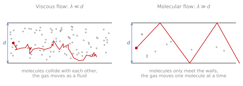
The two flow regimes. When the mean free path is short against the tube, molecules collide with each other and the gas behaves as a fluid; when it is long, each molecule flies wall to wall on its own.
For any charged-particle instrument the beam path is effectively collision-free once the pressure is below roughly 10-5 Torr; the much harder UHV requirement comes entirely from surface cleanliness, and instruments that do not care about surface contamination (a conventional SEM, for example) run comfortably at high vacuum.
The monolayer formation time
The single most useful number in vacuum practice is the time to form one monolayer of adsorbed gas. Dividing a monolayer’s worth of sites (about 1015 per cm) by the impingement flux, with sticking coefficient one, gives for room-temperature nitrogen the rule of thumb
with the time to accumulate one monolayer. At 10-6 Torr a monolayer forms in seconds; at 10-10 Torr it takes on the order of ten hours. Surface-sensitive spectroscopy (XPS, AES, LEIS) and atomically resolved surface imaging (STM, LEED) therefore live in UHV, and every discussion of a technique in this course will note how demanding its vacuum requirements really are. Real sticking coefficients are below one and depend on the gas and surface, so these are worst-case times; they are still the right planning numbers, because the residual gas in a UHV system is dominated by exactly the reactive species (water, CO, hydrogen) that stick well. The calculator below carries the full arithmetic across the pressure range; sliding from atmosphere to UHV, fourteen orders of magnitude, is the fastest way to internalize why vacuum hardware dominates surface analysis.
Vacuum calculator
Conductance, pumping speed, and gas load
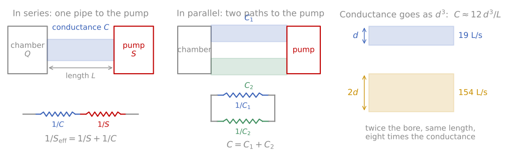
Pumping arithmetic as a resistor network. Left: a pipe and a pump in series, so their reciprocals add. Middle: two paths in parallel, so their conductances add. Right: conductance goes as the cube of the bore, which is why a wider pipe beats a bigger pump.
Vacuum systems are bookkept exactly like resistor networks. A pipe passes a throughput , where is the gas load in Torr·L/s, the pressure difference across the pipe, and its conductance in L/s, so the gas load plays the part of the current, the pressure difference the part of the voltage, and the conductance the part of . A pump is rated by its pumping speed (volume per unit time, liters per second) and is simply one more element in the chain, so conductances in a line add as reciprocals while conductances side by side add directly:
with the steady-state pressure the chamber settles at and the effective speed the chamber actually sees, which the smaller of and controls. A pumping speed and a conductance share units, liters per second, because a pump behaves like a conductance leading to a perfect vacuum. The pump removes a volume of gas per second from its inlet, where the pressure is , so it carries , the same relation as for a pipe. The same gas load passes through the pipe and then into the pump, so the pump inlet sits at . The pipe needs a pressure difference to carry the same gas, and adding the two gives , exactly as two resistors in series add, with and as the resistances. Molecular-flow conductance is set by geometry alone: for an orifice it is proportional to the area times the mean molecular speed, and for a long tube carrying air at room temperature it is L/s with the diameter and the length in cm. The cube is the part worth remembering, since doubling the bore multiplies the conductance by eight while a second identical pipe alongside only doubles it. Hence the cardinal design rule: short, fat connections to pumps, because a long thin bellows can throttle an expensive pump to a fraction of its rated speed, and no larger pump can fix a conductance-limited system.
The gas load has several sources, and which one dominates changes with pressure. Initial pumpdown removes the chamber volume (fast, exponential). What remains is outgassing: gas desorbing from every internal surface, overwhelmingly water in an unbaked chamber, which desorbs so slowly at room temperature that an unbaked system stalls near 10-8 Torr no matter how long it pumps. This is why UHV systems are baked, typically at 120 to 200 °C for many hours while pumping, to drive the water off the walls; after cooldown the residual gas is dominated by hydrogen diffusing out of the bulk of the stainless steel itself, the ultimate background of most UHV systems. Beyond outgassing sit true leaks (openings to atmosphere), virtual leaks (trapped volumes such as unvented screw holes that release gas slowly), and permeation through elastomer seals, which is why UHV practice replaces elastomer O-rings with knife-edge copper-gasket (ConFlat) seals, uses low-vapor-pressure materials throughout, and treats fingerprints as a contamination source on par with a leak.
Pumps
No single pump spans from atmosphere to UHV, so real systems chain several:
Roughing pumps (rotary vane, scroll, diaphragm) work by mechanically trapping and compressing gas, covering atmosphere to the millitorr range, and back turbo pumps continuously. Oil-free (dry) pumps are now standard on analytical instruments because hydrocarbon oil vapor migrating backward into the chamber contaminates every surface analysis.
Turbomolecular pumps use a stack of blades spinning at tens of thousands of rpm; in molecular flow, each blade collision biases the molecule’s direction toward the exhaust, compressing the gas stage by stage. They cover roughly 10-3 to 10-10 Torr and are the workhorse of modern instruments. Their compression ratio is worst for light gases, which is one reason hydrogen dominates deep UHV.
Ion pumps ionize gas molecules in a magnetically confined discharge and bury the ions in sputtered titanium. They have no moving parts, no oil, and no vibration, making them the standard for UHV analysis chambers and for vibration-sensitive instruments such as STM; their pump current even doubles as a pressure reading.
Capture pumps: cryopumps condense and trap gas on surfaces at tens of kelvin (enormous speed for water), titanium sublimation pumps periodically deposit a fresh chemically reactive Ti film that getters active gases, and non-evaporable getter (NEG) coatings extend the same idea to distributed pumping. Capture pumps saturate and need regeneration, so they always operate alongside throughput pumps.
A typical analysis system combines a load lock (so samples enter without venting the analysis chamber), turbo plus dry roughing on the transfer line, and ion plus titanium sublimation pumping on the baked UHV chamber. What each level of hardware reaches, with rough costs for the vacuum hardware alone (chamber, pumps, and gauges, not the instrument mounted on it):
| Hardware | Base pressure (Torr) | Rough cost |
|---|---|---|
| Elastomer seals, scroll or rotary pump only | 10-3 | a few thousand |
| Elastomer seals, turbo backed by a dry pump, unbaked | 10-6 to 10-7 | ten to thirty thousand |
| ConFlat metal seals, turbo, unbaked | 10-8 | fifty thousand and up |
| ConFlat, baked, turbo plus ion pump and TSP | 10-10 to 10-11 | one to several hundred thousand |
| Baked, vacuum-fired or NEG-coated steel, all-metal valves | below 10-12 | specialist research systems |
The expensive stretch is 10-7 to 10-10, and most of what the money buys there is not pumping speed: it is metal seals, materials chosen for low outgassing, and a bakeout that takes the chamber out of service for a day or two every time it is opened. That is the real price of surface sensitivity, and it is why a technique that tolerates high vacuum costs so much less to run.
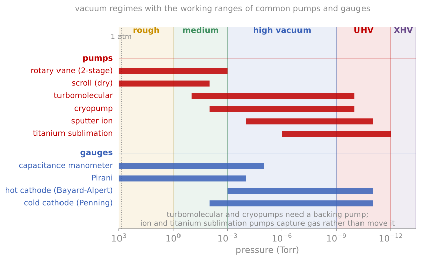
The vacuum regimes with the working range of every common pump and gauge. No single pump or gauge spans the range, which is why systems are staged.
Gauges and residual gas analysis
Pressure measurement changes physics across fourteen decades. Near atmosphere, capacitance manometers measure the actual force on a diaphragm (gas-species independent, the metrology standard). In rough vacuum, Pirani gauges infer pressure from the thermal conductivity of the gas. From high vacuum down, ionization gauges take over: a hot filament emits electrons that ionize residual gas, and the collected ion current is proportional to density. The Bayard-Alpert design, with its fine-wire collector, reads reliably to below 10-10 Torr, with two caveats worth remembering: readings are species-dependent (calibrated for N), and the hot filament itself pumps and outgasses slightly.
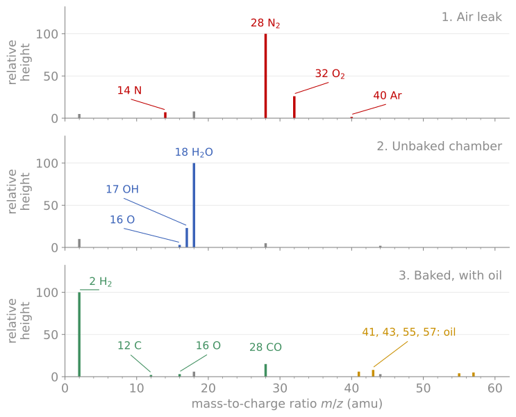
Three residual gas spectra, drawn as peak height against mass-to-charge ratio. An air leak puts masses 28 and 32 in the 4:1 ratio of air with argon at 40; an unbaked chamber is water at 18 with its 17 and 16 fragments; a baked system sits on hydrogen at 2, and the ladder at 41, 43, 55, 57 is pump oil.
The most informative vacuum instrument is the residual gas analyzer (RGA), a small quadrupole mass spectrometer (the same analyzer physics as SIMS) that reports which gases remain. Reading an RGA spectrum is a core lab skill, and one thing has to be understood before the spectrum makes sense: the ionizer uses electrons of about 70 eV, which both ionize molecules and break them apart, so each gas gives a fixed pattern of fragment peaks rather than a single line. That pattern is the cracking pattern, and it is what separates two gases at the same nominal mass.
| Gas | Peaks at | What it tells you |
|---|---|---|
| H | 2 | The floor of a well-baked stainless system: hydrogen diffusing out of the steel |
| HO | 18, with 17 (OH) and 16 (O) | Wall outgassing in an unbaked chamber, the dominant load below 10-6 Torr |
| N | 28, with a small 14 (N) | Air, if 32 and 40 come with it |
| O | 32 | Only comes from air |
| Ar | 40 | 1% of air, so about 1% of the 28 peak |
| CO | 28, with 12 (C) and 16 (O) | Baked systems and electron-stimulated desorption, not a leak |
| CO | 44, with 28, 16, 12 | Bake product |
| Hydrocarbons | ladder at 41, 43, 55, 57 and up | Pump oil backstreaming, or a dirty part |
Mass 28 is the one to be careful with, because N and CO sit on top of each other: the 12 and 16 fragments with no 32 say CO, while 32 and 40 companions say air. A leak shows N and O in their 4:1 atmospheric ratio, while outgassing shows water, and this single diagnostic separates the two most common vacuum problems in minutes.
References and further reading
J. F. O’Hanlon, A User’s Guide to Vacuum Technology, 3rd ed., Wiley (2003). The standard practical reference for everything on this page.
K. Oura et al., Surface Science: An Introduction, Springer (2003), Chapter 2.
L. C. Feldman and J. W. Mayer, Fundamentals of Surface and Thin Film Analysis, North-Holland (1986), Chapter 1.