
X-ray reflectivity (XRR) measures the specular reflection of X-rays from a film at angles of a fraction of a degree to a few degrees. It is one of the most precise thickness measurements available anywhere, routinely better than 1%, and it works on amorphous and crystalline films alike because it depends only on electron density, not on crystallinity. Together with its diffuse-scattering cousins GISAXS and GIWAXS, it forms the grazing-incidence family of measurements that probe film thickness, density, roughness, and nanoscale morphology. This page develops the physics from the refractive index up, because every feature of a reflectivity curve maps onto one term of that physics.
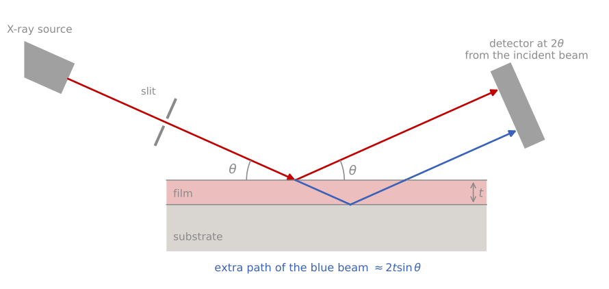
The XRR measurement. The beam strikes the sample at a grazing angle , and the detector records the beam reflected at the same angle, from the incident beam. During the scan the incidence and exit angles stay equal: either the source and detector each tilt by above a fixed sample, or the sample turns by and the detector by . A film reflects twice, at its surface (red) and at the buried interface (blue), and the blue beam travels an extra . Angles are exaggerated.
| At a glance | |
|---|---|
| Probe in / signal out | X-rays in at grazing incidence, reflected or scattered X-rays out |
| Information | Layer thickness, density, interface roughness (XRR); lateral nanostructure (GISAXS); crystalline packing in thin and organic films (GIWAXS) |
| Depth probed | Total stack up to a few hundred nanometers |
| Lateral resolution | Averages over the beam footprint, millimeters |
| Sensitivity | Thickness to about 1%; density to a few percent; roughness to fractions of a nanometer |
| Sample requirements | Smooth, flat samples; measured in air, nondestructive |
The refractive index of matter for X-rays
At X-ray frequencies, far above the resonances of most bound electrons, the electrons of a solid respond to the driving field like free charges, slightly out of phase, and the refractive index dips just below one:
where is the complex refractive index, the amount by which its real part falls below one, the X-ray wavelength, m the classical electron radius, and the electron density; encodes absorption. For Cu K radiation is of order 10-5: solids are optically thinner than vacuum, but only just. Because , the index is a direct, chemistry-independent measure of mass density, which is what makes XRR one of the very few density probes for thin films.
An index below one has an important consequence. Just as light inside glass totally reflects at a glancing internal angle, X-rays arriving from vacuum totally reflect from any solid below a critical angle
typically 0.2° to 0.6°. Below the transmitted wave is evanescent, penetrating only a few nanometers, a fact exploited by grazing-incidence techniques to achieve surface sensitivity with a deeply penetrating probe. Above the reflectivity of an ideally sharp surface falls off steeply; from the Fresnel equations, the reflection amplitude between media with vertical wavevectors and is , which for gives the workhorse asymptote
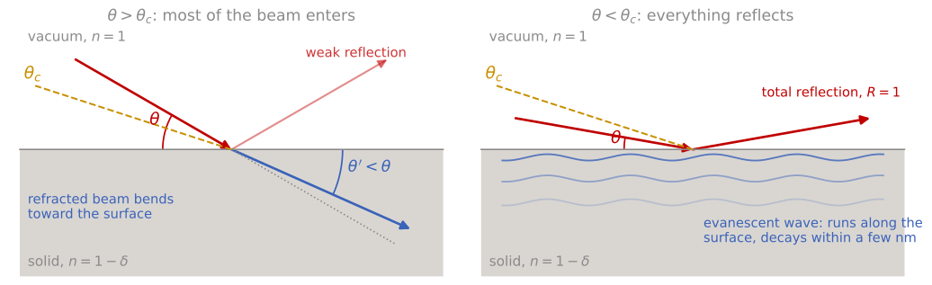
Refraction and total external reflection. The dashed line marks the critical angle . Left: a beam steeper than enters the solid and bends toward the surface, to a smaller angle , because , and only a small fraction reflects. Right: a beam shallower than is reflected completely, and an evanescent wave runs along the surface and decays within a few nanometers. Angles are exaggerated; real critical angles are below 1°.
where is the fraction of the incident intensity reflected at incidence angle , and is the critical angle. The decay (equivalently , the same power law as Porod scattering from sharp interfaces) means the signal drops seven or eight decades across a measurement, which sets the instrumental demands discussed below.
One film: Kiessig fringes
Add a film and there are two reflecting interfaces. The two reflected amplitudes interfere with a phase difference set by the optical path through the film, producing thickness oscillations (Kiessig fringes). Including refraction, the fringes sit at angles satisfying , with the fringe order and the critical angle of the film; well above the critical angle the period settles to
with the angular spacing of successive fringes, the X-ray wavelength, and the film thickness, so a 50 nm film measured with Cu K shows fringes about 0.09° apart, and the refraction correction compresses the first few fringes just above (the effect is visible in the simulator below). Reading the period gives the thickness immediately, with a precision that comes from counting many fringes; this is why XRR thickness values carry sub-percent error bars. The fringe amplitude is set by the electron-density contrast between film and substrate: a dense film on a light substrate (or vice versa) gives deep fringes, while a density-matched film gives almost none, and a film denser than its substrate shows its own higher critical angle as a visible shoulder.
Whether this condition marks the fringe maxima or the minima depends on the density step at the buried interface. Each reflected amplitude takes the sign of the change in electron density at its interface, and at the top surface the density always rises. If the substrate is denser than the film, as for SiO on Si, the density also rises at the buried interface, both reflections have the same sign, and the condition gives the fringe maxima. If the film is denser than the substrate, as for W, TiN, or Cu on Si, the density falls at the buried interface, that reflection changes sign, and the condition gives the fringe minima; this is the same half-wave shift that sets the colors of a soap film. The fringe spacing is the same in both cases, so the thickness does not depend on the choice. Using the wrong set of extrema assigns each fringe an order that is off by one half, which shifts the intercept of a plot of against , and therefore the film density.
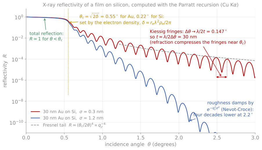
Every feature of a reflectivity curve and what sets it: the total-reflection plateau, the critical angle from electron density, the Fresnel tail, the fringe period from thickness, and the roughness damping.
Multilayers, the master formula, and Parratt
For an arbitrary stack the exact reflectivity is computed by the Parratt recursion: starting from the substrate, the reflection amplitude of each interface is combined with the phase accumulated crossing each layer, exactly as in thin-film optics. This is the calculation every fitting program (and the simulator below) performs. A complementary approximation carries most of the intuition: in the kinematic limit (weak reflection, valid above roughly ),
where is the momentum transfer normal to the surface, the Fresnel reflectivity of an ideally sharp surface, the electron density at depth , and its value deep in the substrate. The reflectivity is the Fresnel decay times the Fourier transform of the electron-density gradient. Everything about a reflectivity curve follows from this statement: sharp interfaces contribute strongly at all (hence persists), a film of thickness has two gradient spikes separated by (hence fringes of period in ), and any smearing of an interface kills the high- signal (hence the roughness damping next).
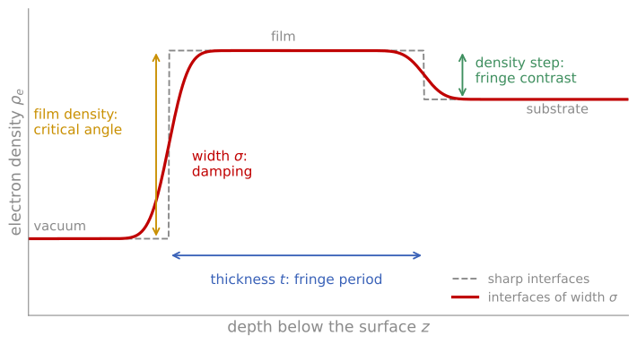
The electron density profile that XRR measures, for a film denser than its substrate. The film density sets the critical angle, the thickness sets the fringe period, the density step at the buried interface sets the fringe contrast, and the interface widths damp the curve.
Roughness and diffuse scattering
A rough or graded interface spreads the density gradient over a width , damping its reflection amplitude by a Gaussian factor, in the standard Névot-Croce form . Two distinct signatures let a fit separate the interfaces: roughness of the top surface accelerates the decay of the whole curve, while roughness of a buried interface damps the fringe amplitude without changing the overall envelope. Crucially, specular XRR cannot distinguish true roughness from compositional grading; both smear the density profile, and only the diffuse scattering can tell them apart, since grading scatters nothing off-specular while roughness does.
That diffuse scattering is a measurement in its own right. Rocking the sample at fixed detector angle separates the sharp specular ridge from the diffuse background, whose shape encodes the lateral correlation length of the roughness, and which characteristically peaks when the incidence or exit angle passes through (the Yoneda wings, an enhancement caused by the standing-wave field at the critical angle). For most film metrology the practical point is simpler: fit the specular curve, and treat as an interface width that lumps roughness and grading together.
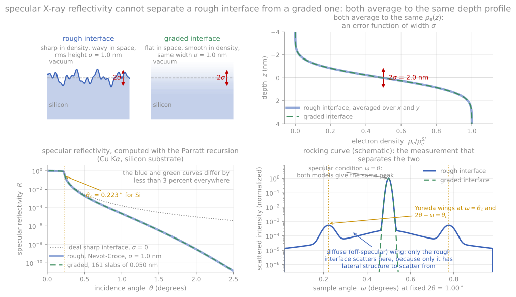
A rough interface and a graded interface of the same width give the same averaged density profile and nearly the same specular curve. Only the rough one scatters diffusely, which is what breaks the degeneracy.
Accurate measurements
Three practicalities dominate real XRR work. First, footprint: at 0.2° incidence the beam spills over any sample shorter than tens of millimeters, so low-angle intensities need a geometric correction and small samples give distorted critical-angle regions. Second, dynamic range: following the signal down seven decades requires automatic attenuators for the direct beam and low backgrounds; the accessible thickness ceiling (a few hundred nanometers) is set by how finely the instrument can resolve the closing fringe spacing. Third, fitting: parameters correlate, thickness is robust because it is a frequency, but density and roughness both act on amplitudes, and a good fit starts from a physically sensible model of the stack, including layers you did not intend to have (native oxides, surface contamination). When an XRR fit and an ellipsometry fit of the same film agree on thickness, both models gain credibility; the two techniques share the interference physics but weight the interfaces entirely differently.
XRR calculator
The calculator below computes the exact Parratt reflectivity of a film on silicon as you adjust the stack. Work through the fitting logic one parameter at a time: thickness sets the fringe period, density sets the critical angle and the fringe contrast against the substrate, surface roughness accelerates the overall decay, and interface roughness damps the fringes without changing their period. These four signatures are exactly what an XRR fitting program is disentangling, and seeing them separately is most of the skill of reading a reflectivity curve.
GISAXS and GIWAXS
Replacing the point detector with an area detector at grazing incidence turns reflectivity into scattering. GISAXS (grazing-incidence small-angle X-ray scattering) records the diffuse scattering at small angles around the specular beam, which encodes lateral structure on the 1 to 100 nm scale: island sizes and spacings during growth, pore networks in low-k dielectrics, and the domain spacing of self-assembled block copolymer films. Because the incidence angle sits near , the technique is surface-selective yet averages over square millimeters, a statistical power no microscopy matches; quantitative analysis uses the distorted-wave Born approximation to handle the reflection-enhanced fields. GIWAXS (wide-angle) records the diffraction rings of the film with the same surface sensitivity and, critically, resolves their orientation: a spot pattern versus a ring immediately distinguishes an oriented crystalline film from a powder-like one. It has become the standard structural probe of organic photovoltaics, halide perovskites, and other solution-processed films, where the texture and polymorph of a spin-cast layer decide device performance. Both are most powerful at synchrotrons, where high flux permits real-time measurements during film growth, annealing, and solvent drying.
Neutron reflectometry follows the same formalism with the electron density replaced by the neutron scattering-length density, which depends on the nucleus rather than on and differs strongly between isotopes. Deuterium labeling therefore creates contrast between chemically identical layers, making neutrons the technique of choice for polymer interdiffusion and buried organic interfaces; with polarized neutrons the magnetic contribution to the scattering length resolves the depth profile of magnetization in multilayers, a measurement nothing else provides nondestructively.
References and further reading
M. Birkholz, Thin Film Analysis by X-Ray Scattering, Wiley-VCH (2006), Chapter 4.
J. Als-Nielsen and D. McMorrow, Elements of Modern X-ray Physics, 2nd ed., Wiley (2011), Chapter 3. The refractive-index and Fresnel treatment followed here.
L. G. Parratt, Surface studies of solids by total reflection of X-rays, Physical Review 95, 359 (1954). Parratt (1954)
G. Renaud, R. Lazzari, and F. Leroy, Probing surface and interface morphology with grazing incidence small angle X-ray scattering, Surface Science Reports 64, 255 (2009). Renaud et al. (2009)
- Parratt, L. G. (1954). Surface Studies of Solids by Total Reflection of X-Rays. Physical Review, 95(2), 359–369. 10.1103/physrev.95.359
- Renaud, G., Lazzari, R., & Leroy, F. (2009). Probing surface and interface morphology with Grazing Incidence Small Angle X-Ray Scattering. Surface Science Reports, 64(8), 255–380. 10.1016/j.surfrep.2009.07.002